3.10 - Investigating Resistance
The standard test circuit
-
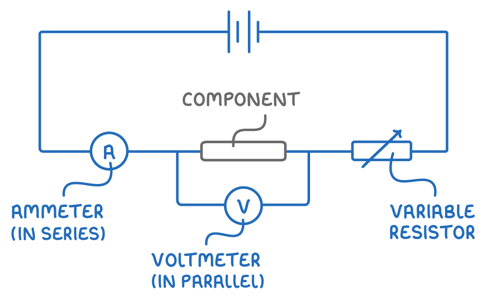
To find out how a component behaves, its current and potential difference are measured at the same time using a standard test circuit.
-
The same circuit works for a fixed resistor, a filament lamp or a diode.
-
Ammeter - Measures the current through the component, in amps. Placed in series with the component, so the same current passes through both. It can go anywhere along the main circuit, but never in parallel.
-
Voltmeter - Measures the potential difference across the component, in volts. Placed in parallel with the component being tested, not across the battery or any other part.
Taking the readings
- Connect the component and the ammeter in series, with the voltmeter in parallel across the component.
- Vary the current through the component - usually by adjusting a variable resistor in series, as shown below, or by changing the output potential difference of the power supply.
- Record several pairs of current and potential difference readings as the current is changed.
- For each pair, calculate the resistance (). This shows whether the resistance stays constant or changes with current.
Keeping the results reliable
- The component can heat up as current flows, and a change in temperature changes its resistance.
- Keep the current low, and disconnect the circuit to cool between readings if it starts to warm up.
- Repeat each reading and calculate a mean.
Measuring resistance directly with an ohmmeter
- The standard test circuit finds resistance indirectly, by measuring current and potential difference and then using .
- Resistance can also be measured directly with an ohmmeter, usually one of the settings on a multimeter.
How to use it
- Switch the meter to its resistance (ohms) setting and choose a sensible range.
- Disconnect the component from its circuit. The ohmmeter supplies its own small current, so any external power supply must be disconnected to avoid damaging the meter or getting a false reading.
- Connect the two leads of the ohmmeter across the component.
- Read the resistance directly from the display, in ohms.
When to use each method
- Ohmmeter - Quicker when you just need a single value.
- Test circuit - Needed when you want to see how a component's resistance changes with current or temperature.
Investigating resistors in series and in parallel
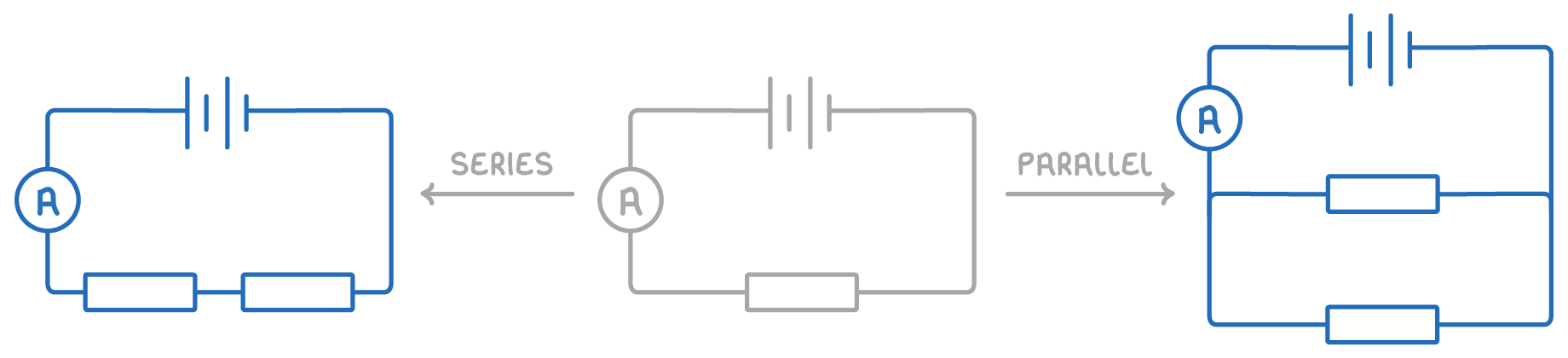
The effect of adding resistors is investigated by building up a circuit one identical resistor at a time and finding the total resistance at each step.
Adding resistors in series
- Build the circuit with one resistor and note the potential difference of the power supply.
- Measure the current through the circuit and calculate the total resistance ().
- Add another identical resistor in series with the first.
- Measure the current again and calculate the new total resistance.
- Repeat for several resistors and plot a graph of total resistance against the number of resistors.
Adding resistors in parallel
Follow the same method, but connect each new resistor in parallel with the first rather than in series.
The expected pattern
- Each resistor added in series increases the total resistance and decreases the current.
- Each resistor added in parallel decreases the total resistance and increases the current.