3.11 - Potential Dividers
A potential divider shares a voltage between two resistors
- A potential divider is a circuit that splits a supply voltage between two resistors in series.
- It allows a circuit to take a smaller voltage from a larger supply.
- The supply's potential difference is shared between the two resistors in the ratio of their resistances: the larger a resistor's share of the total resistance, the larger its share of the voltage.
Because the same current passes through both resistors in series, a larger resistance has a larger potential difference across it.
Worked through with numbers
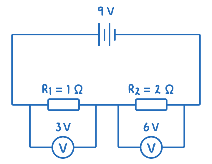
A 9 V supply is connected across a 2 Ω resistor and a 1 Ω resistor in series, as shown in the circuit below.
- Total resistance = 2 + 1 = 3 Ω.
- The 2 Ω resistor takes 2/3 of the supply: 2/3 of 9 V = 6 V.
- The 1 Ω resistor takes 1/3 of the supply: 1/3 of 9 V = 3 V.
- The two shares add up to the 9 V supply.
The potential-divider ratio equation
For two resistors in a potential divider, the ratio of the resistances equals the ratio of the potential differences across them.
Ratio equation
Where:
- = The two resistances, in ohms (Ω)
- = The potential differences across and , in volts (V)
The two potential differences always add up to the supply: .
Worked example - Using the ratio equation
A potential divider has a 15 V supply. is 25 Ω and is 50 Ω, and a voltmeter reads 5 V across . Use the ratio equation to find the potential difference across .
Step 1 - Write down the ratio equation
Step 2 - Rearrange and substitute to find V2
The potential difference across is 10 V.
The two shares add up to the supply: .
Varying the output with a variable resistor
Replacing one fixed resistor with a variable resistor lets the output voltage be adjusted while the circuit runs.
- With the variable resistor set to zero, almost the whole supply voltage appears across the fixed resistor, so the output is close to the full supply.
- As the variable resistance increases, it takes a larger share of the supply, and the output across the fixed resistor falls.
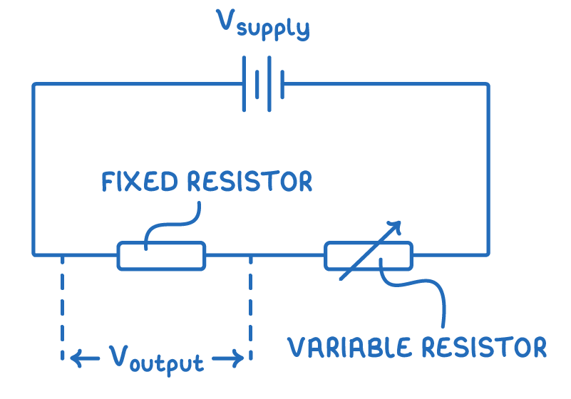
The output voltage formula
Where:
- = The output potential difference across , in volts (V)
- = The two resistances, in ohms (Ω)
- = The supply potential difference, in volts (V)
The output depends on the relative sizes of the resistors:
- If is much larger than , the output is close to the full supply voltage.
- If is much smaller than , the output is close to zero.
Worked example - Finding the output voltage
A potential divider has a 15 V supply. is 25 Ω and is 50 Ω. A device is connected across . What output voltage does it receive?
Step 1 - Write down the values
= 15 V, = 25 Ω, = 50 Ω.
Step 2 - Substitute into the output voltage equation
The device receives an output of 10 V.
Sensing circuits with an LDR or thermistor
- A potential divider becomes a sensing circuit when one resistor is replaced by a component whose resistance changes with its surroundings:
- Thermistor - Resistance changes with temperature.
- Light-dependent resistor (LDR) - Resistance changes with light level.
- The output voltage then changes automatically with the conditions.
Example - A temperature-controlled fan
A thermistor is placed in series with a fixed resistor, and a fan is connected across the fixed resistor.
- As the room warms up, the thermistor's resistance falls, so it takes a smaller share of the supply voltage.
- The voltage across the fixed resistor (and the fan) rises, so the fan runs faster.
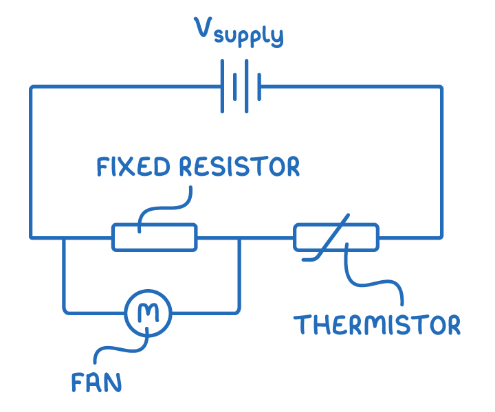
Replacing the thermistor with an LDR gives a circuit that responds to light instead of temperature in the same way.