25.10 - Circuit Diagrams & Electrical Measurements
Electrical circuit questions
Electrical practical questions are built on measuring the current through a component using an ammeter, the potential difference across it using a voltmeter, and finding resistance using .
Common question types
- Adding a meter to a circuit - e.g. adding a voltmeter to measure the potential difference across a resistor.
- Drawing a component symbol - e.g. drawing the symbol for a thermistor or variable resistor.
- Drawing a complete circuit from a description - e.g. drawing three lamps connected in series.
- Identifying a circuit fault - e.g. explaining why an ammeter reads zero when the switch is closed.
A typical question
The student replaces the fixed resistor with a component that lets him change the current smoothly. Draw the circuit symbol for this component. [1]
Circuit symbols and meter placement
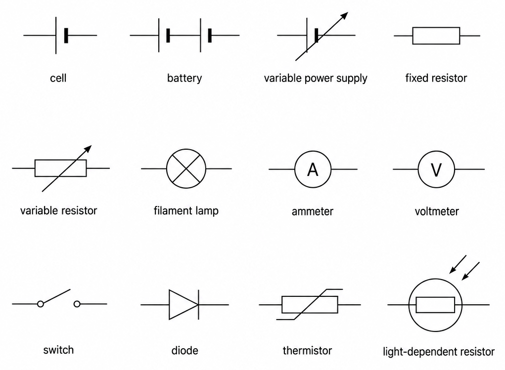
Circuit symbols
| Component | Symbol | Notes |
|---|---|---|
| Cell | A long thin line and a short thick line | The long line is the positive terminal |
| Battery | Two or more cells connected in series | |
| Variable power supply | A cell symbol with a diagonal arrow through it | |
| Fixed resistor | A plain rectangle | |
| Variable resistor | A rectangle with a diagonal arrow through it | |
| Filament lamp | A circle with a cross inside | The cross must touch the circle |
| Ammeter | A circle with a capital A inside | |
| Voltmeter | A circle with a capital V inside | |
| Switch | A gap in the wire with a hinged line | |
| Diode | A triangle pointing at a vertical line | The triangle points in the direction of conventional current flow |
| Thermistor | A rectangle with a diagonal line through it, bent at the bottom | |
| Light-dependent resistor (LDR) | A rectangle with two arrows pointing inward |
Where meters go
- Ammeter - Connected in series (in the main loop) to measure the current through a component.
- Voltmeter - Connected in parallel (across the component) to measure the potential difference across it.
To check: if you can trace a path from the power source and back without passing through the meter, it's in parallel. If you must pass through the meter, it's in series.
Meter placement errors
- Voltmeter in series - A voltmeter has very high resistance, so putting it in series stops almost all current. The ammeter will read close to zero, and the voltmeter will read close to the supply voltage.
- Ammeter in parallel - An ammeter has very low resistance, so putting it in parallel short-circuits the component.
Why use a variable resistor?
It allows you to adjust the current continuously to take a series of readings at different currents and potential differences.
Drawing and fault-finding in circuits
Adding meters to a circuit diagram
- Ammeter - Insert in series directly into the wire loop.
- Voltmeter - Connect in parallel by drawing two leads across the specific component.
Drawing circuits from a description
- Draw circuits with straight lines, square corners, and clear symbols.
- Series - All components are connected in a single continuous loop.
- Parallel - The wire splits into separate branches, each containing a component, before joining back together.
Common circuit faults
| Symptom | Likely cause |
|---|---|
| Ammeter reads zero with switch closed | A break in the circuit, or a component (such as a diode) connected backwards |
| Ammeter reads close to zero, voltmeter reads close to the supply voltage | Voltmeter connected in series instead of parallel |
| Meter reading is negative / needle deflects backwards | Meter terminals connected the wrong way round |
| Component doesn't work and ammeter reading is unusually high | Ammeter connected in parallel across the component, causing a short circuit |
If a circuit contains a diode and the ammeter reads zero, the diode, power supply, or ammeter is connected the wrong way round.
Practical techniques
- Read both meters at the same time before adjusting the variable resistor, so that the values of and correspond to the same state.
- Switch off between readings - Current heats the wires and components, which increases their resistance. Switching off keeps the temperature and resistance constant.
Common exam questions
Question 1
Where does an ammeter go in a circuit, and why?
In series, in the wire itself, so that all the current passing through the component also passes through the meter. Current is a flow through a wire, so to measure it the meter has to be in the flow.
Question 2
Where does a voltmeter go, and why?
In parallel, connected across the component, with one lead on each side of it. Potential difference is a difference between two points, so the meter has to be connected to both.
Question 3
A student connects a voltmeter in series in the main loop. What happens to the readings?
The ammeter reads close to zero and the voltmeter reads close to the supply voltage. A voltmeter has a very high resistance, so putting it in the loop almost stops the current, and the circuit looks as though it is not working.
Question 4
Describe the circuit symbol for a variable resistor.
A rectangle with an arrow drawn diagonally through it. The arrow is what distinguishes it from a fixed resistor, which is a plain rectangle.
Question 5
Give one advantage of using a variable resistor in this experiment.
It lets you set the current to any value you choose, smoothly and easily, so you can take a series of readings at different currents rather than being limited to whatever the supply provides.
Question 6
The ammeter reads zero when the switch is closed, and the circuit contains a diode. Suggest what has gone wrong.
The diode has been connected the wrong way round, so it is blocking the current. Connecting the power supply or the ammeter the wrong way round would have the same effect.
Question 7
How can you check by eye whether a meter is in series or in parallel?
Trace the wire from one terminal of the battery all the way round and back. If you can complete the loop without going through the meter, it is in parallel; if you cannot, it is in series.
Question 8
Why should the power supply be switched off between readings?
Because current flowing through a wire heats it, and a hot wire has a higher resistance. Switching off between readings keeps the wire at a steady temperature so the readings are taken under the same conditions.
Question 9
A student draws three lamps side by side in a single loop and labels the diagram "parallel". What is wrong?
There is no split in the circuit, so they are in series. In a parallel circuit the loop divides, each lamp sits in its own branch, and the branches join again before the supply.