25.11 - Ray-Trace Experiments - Normals, Pins & Angles
What an optics question looks like
In an optics practical question, you draw normals, rays, and lines on a printed ray-trace sheet using a pencil, ruler, and protractor, then take measurements and calculate values.
Where the marks fall
- Drawing marks - Normal drawn perpendicular to the surface and labelled; rays drawn at stated angles within tolerance; lines fine and straight.
- Measurement marks - Angles (accepted within ± 1° to ± 2°) or lengths (within ± 0.1 cm) read directly from your drawing.
- Calculations - Ratios of lengths or refractive index.
- Technique and evaluation - Explaining precautions, pin spacing, or sources of experimental error.
A typical question
- On Fig. 3.1, draw the normal through the centre of .
- Continue the normal so that it passes through the curved side of the block.
- Label the normal .
- Label the point where the normal crosses . [1]
Draw a line 7.0 cm long from at an angle of incidence to the normal, below and to the left of the normal. Label the end of this line . [1]
The normal, and measuring angles to it
The normal is a line drawn at right angles (90°) to the surface at the point where the ray meets it.
Drawing the normal
- Draw it perpendicular to the surface, not the page edge, using a protractor or set square.
- Pass through the exact point specified by the question.
- Draw a thin line with a sharp pencil, and label it as instructed.
Measuring and drawing angles
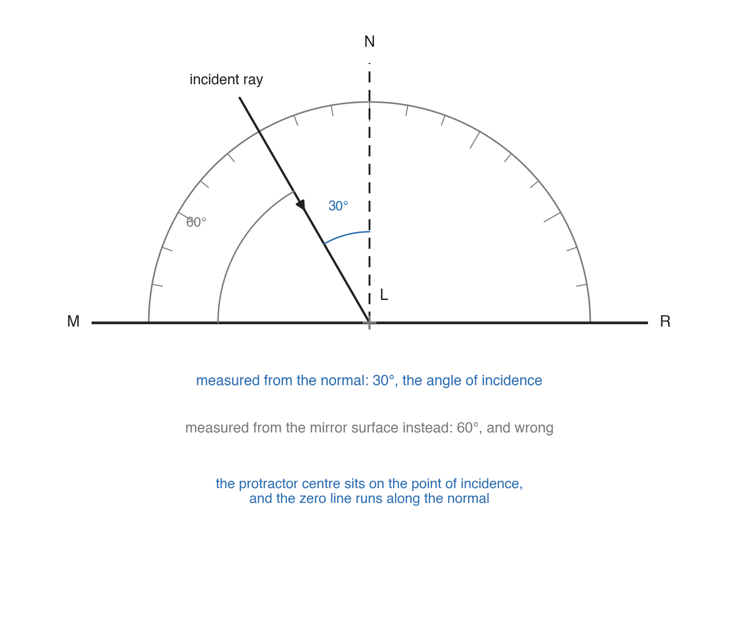
- All angles in optics are measured between the ray and the normal, never the surface.
- If you measure from the surface, your angle will be .
- Using a protractor - Place the centre on the point of incidence, line the zero along the normal, and read the angle to the ray on the correct scale.
- Drawing an angle - Align zero with the normal, mark the specified angle on the correct side, and rule a straight line from the point of incidence through the mark.
Drawing precision
Use a sharp pencil and a ruler so lines are thin, straight, and single.
Setting up - Optics pins and the lens bench
Optics pins
Pins mark the path of a ray of light across a sheet of paper.
Key rules:
- Keep pins at least 5 cm apart (up to about 15 cm). Greater separation reduces the effect of small marking errors and defines the ray direction more accurately.
- Keep pins upright so the pin heads stay directly above the holes.
- View the bases of the pins at eye level near bench height, aligning them so one pin hides the others.
The lens bench
Used to measure focal length or magnification using an illuminated object, a converging lens, and a screen.
Alignment precautions:
- Object, lens, and screen must be at the same height and centred on the same axis.
- Lens and screen must be perpendicular to the bench.
- Clamp the metre rule to the bench so distances don't shift.
Finding a sharp image: Move the screen slowly back and forth through the clearest focus to find the centre of the sharpest range.
Measuring image height:
- Difficulty - Your hand or ruler blocks the light hitting the screen.
- Improvements - Use a translucent screen and measure from behind, or stick grid paper onto the screen to read the height directly.
Sources of experimental error
- Thickness of pins and drawn pencil lines.
- Difficulty judging the exact centre of a pin hole or ray line.
- Protractor resolution (typically readable only to the nearest 1°).
Common exam questions
Question 1
What is the normal, and where is it drawn?
A line at right angles to the surface, drawn through the point where the ray meets it. Every angle in the question is measured from it.
Question 2
A student measures an angle of incidence as 60° where the expected answer is 30°. What has probably gone wrong?
They measured from the mirror surface instead of from the normal. The two angles always add up to 90°, so an answer and the expected value adding to 90 is the signature of this mistake.
Question 3
How should a protractor be positioned to measure an angle of incidence?
With its centre exactly on the point where the ray meets the surface, and its zero line along the normal. Then read the scale where the ray crosses it, checking you are reading the scale that starts from the normal.
Question 4
Suggest a suitable distance between two optics pins on a ray-trace sheet.
Anything from about 5 cm to about 15 cm. Cambridge asks for at least 5 cm and no more than 15 cm.
Question 5
Why should the pins be placed far apart?
Because the line is drawn through the two pin holes, so the further apart they are, the less a small error in the position of either hole affects the direction of the line. It also makes them easier to line up by eye.
Question 6
Why should you view the bottoms of the optics pins rather than the tops?
Because the bottom of the pin is where it meets the paper and where the hole is. If a pin leans, its top is not directly above its hole, so lining up the tops puts your line in the wrong place.
Question 7
State two precautions to take when drawing on a ray-trace sheet.
Use a sharp pencil so the lines are thin, and keep the pins upright. Placing the pins as far apart as the sheet allows is also accepted.
Question 8
Describe how a student obtains a sharp image on a screen with a converging lens.
Move the screen slowly backwards and forwards through the position where the image looks sharp, and settle on the middle of the range over which it stays sharp.
Question 9
Give two precautions for setting up a lens, an object, and a screen on a bench.
Have the object, the lens, and the screen all at the same height, and keep the lens and the screen perpendicular to the bench. Fixing the metre rule to the bench so the distances stay comparable is also accepted.
Question 10
Describe one difficulty in measuring the height of an image on a screen, and suggest an improvement.
The difficulty is that your hand and the ruler block the light from the lens while you measure. The improvement is to use a translucent screen and measure the image from behind, or to fix a printed grid to the screen and read the height from that.
Question 11
Suggest one reason why the angles measured in a ray-trace experiment may not be exact.
The pins and the drawn lines both have a thickness, so the line through the pin holes may not be exactly along the ray, and the protractor can only be read to the nearest degree.