10.1 - Logic Gates
Introduction to Boolean logic and logic gates
Boolean logic is a system of rules used in computing to make decisions based on true or false values, represented as 1 (true) or 0 (false). It forms the foundation for how computers process information through simple operations.
Logic gates are electronic circuits built into computer chips that perform these Boolean operations. They take binary inputs (0s and 1s), apply a specific Boolean rule, and produce a binary output. This process is essential for tasks like decision-making in programs and controlling hardware.
Logic diagrams use symbols to represent these gates and show how they connect in circuits. Each gate has a unique symbol and a truth table, which lists all possible input combinations and their outputs.
The NOT gate
The NOT gate is the simplest logic gate, performing the Boolean NOT operation. It inverts the input value, meaning it changes a 0 to a 1 or a 1 to a 0. This is useful in computing for tasks like flipping binary states or creating conditions where something happens only if a value is false.
Symbol for the NOT gate

The symbol is a triangle with a small circle at the output point. A single line enters from the left (input), and another exits from the right (output).
Truth table for the NOT gate
| Input | Output |
|---|---|
| 0 | 1 |
| 1 | 0 |
As shown, the output is always the opposite of the input. For example, if the input is 1, the output is 0.
The AND gate
The AND gate performs the Boolean AND operation, which requires both inputs to be true (1) for the output to be true. If either input is 0, the output is 0. This gate is commonly used in programs to check if multiple conditions are met simultaneously, such as in security systems where two factors must be valid.
Symbol for the AND gate
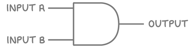
The symbol resembles a capital 'D' shape, with a flat left side and a curved right side. Two lines enter from the left (inputs A and B), and one line exits from the right (output).
Truth table for the AND gate
| Input A | Input B | Output |
|---|---|---|
| 0 | 0 | 0 |
| 0 | 1 | 0 |
| 1 | 0 | 0 |
| 1 | 1 | 1 |
The output is 1 only when both inputs are 1; otherwise, it is 0.
The OR gate
The OR gate carries out the Boolean OR operation, producing a 1 if at least one input is 1. The output is 0 only if both inputs are 0. In programming, this is helpful for scenarios where any one of several conditions can trigger an action, like activating a light if either a motion sensor or a switch is on.
Symbol for the OR gate
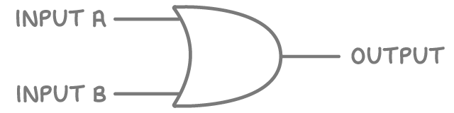
The symbol looks like a crescent shape with a concave left side and a pointed right side. Two lines enter from the left (inputs A and B), and one line exits from the right (output).
Truth table for the OR gate
| Input A | Input B | Output |
|---|---|---|
| 0 | 0 | 0 |
| 0 | 1 | 1 |
| 1 | 0 | 1 |
| 1 | 1 | 1 |
The output is 1 if either or both inputs are 1.
Applying logic gates in computing
Logic gates are fundamental to how computers work, as they process binary data in everything from simple calculations to complex algorithms. By combining gates into circuits, more advanced operations can be created, such as adders or memory units.
In programming, the same Boolean principles apply without physical gates. For example, you might use an if statement with AND to check multiple conditions: if (condition1 AND condition2). This mirrors how hardware gates function, allowing software to make logical decisions based on inputs.