10.2 - Logic Circuits
Combining logic gates for complex operations
Logic gates are the building blocks of digital circuits, and they can be connected together to perform more advanced tasks. A logic circuit is a network of these gates where the output of one gate becomes the input for another.
By linking gates, you create circuits that process multiple inputs through a series of operations. These circuits can be described using Boolean algebra, which uses operators like AND, OR, and NOT to represent the logic.
Key principles of combined logic circuits
- Order of operations - Just like in mathematics, brackets in Boolean expressions show which operations happen first. For example, in NOT(A AND B), the AND operation is done before the NOT.
- Levels in circuits - The "level" refers to the maximum number of gates an input must pass through to reach the output. Simple combinations often form two-level circuits.
Writing logic circuits as Boolean expressions
Boolean expressions use the operators AND, OR, and NOT to describe how inputs are processed in a circuit. These expressions make it easier to analyse and simplify logic without drawing the full diagram.
Example: NOT(AND) circuit

Consider a circuit where two inputs, A and B, go through an AND gate, and the result then passes through a NOT gate. This can be written as P = NOT(A AND B).
The truth table shows all possible input combinations and the output:
| A | B | A AND B | P = NOT(A AND B) |
|---|---|---|---|
| 0 | 0 | 0 | 1 |
| 0 | 1 | 0 | 1 |
| 1 | 0 | 0 | 1 |
| 1 | 1 | 1 | 0 |
Example: NOT(OR) circuit

Now imagine inputs C and D entering an OR gate, followed by a NOT gate. The expression is Q = NOT(C OR D).
The corresponding truth table is:
| C | D | C OR D | Q = NOT(C OR D) |
|---|---|---|---|
| 0 | 0 | 0 | 1 |
| 0 | 1 | 1 | 0 |
| 1 | 0 | 1 | 0 |
| 1 | 1 | 1 | 0 |
These examples are two-level circuits because inputs pass through at most two gates to produce the output.
Logic circuits with more than two inputs
Logic circuits are not limited to two inputs. They can handle three or more, which increases the number of possible combinations and requires larger truth tables.
Example: three-input circuit
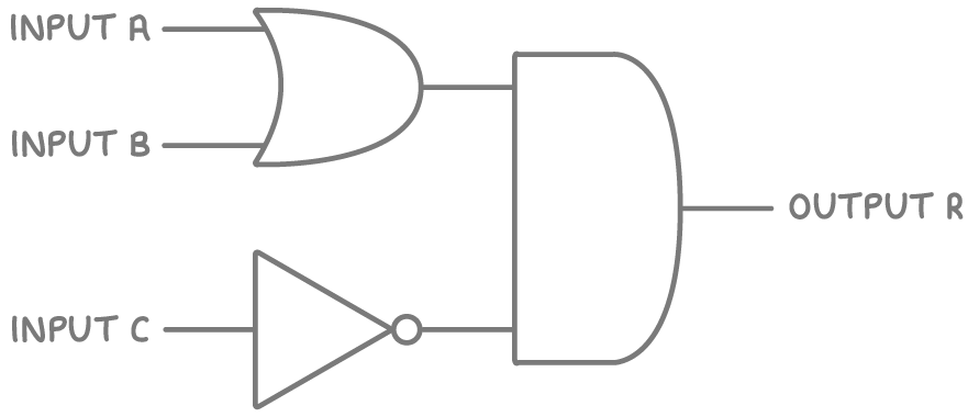
Take a circuit with inputs A, B, and C. Here, A and B go into an OR gate, C goes into a NOT gate, and those results feed into an AND gate. The Boolean expression is R = (A OR B) AND (NOT C).
To build the truth table, list all combinations. With three inputs, each having 2 possible values (0 or 1), there are 23 = 8 rows.
| A | B | C | A OR B | NOT C | R = (A OR B) AND (NOT C) |
|---|---|---|---|---|---|
| 0 | 0 | 0 | 0 | 1 | 0 |
| 0 | 0 | 1 | 0 | 0 | 0 |
| 0 | 1 | 0 | 1 | 1 | 1 |
| 0 | 1 | 1 | 1 | 0 | 0 |
| 1 | 0 | 0 | 1 | 1 | 1 |
| 1 | 0 | 1 | 1 | 0 | 0 |
| 1 | 1 | 0 | 1 | 1 | 1 |
| 1 | 1 | 1 | 1 | 0 | 0 |
Constructing truth tables for multi-input circuits
A truth table lists every possible input combination and the resulting output, helping to verify how a circuit behaves. For circuits with multiple inputs, the table grows exponentially.
Steps to create a truth table
- Identify the number of inputs (n).
- Calculate the rows needed: 2n (e.g., 4 rows for 2 inputs, 8 for 3).
- List all binary combinations for the inputs.
- For each row, calculate intermediate outputs step by step based on the gates.
- Determine the final output using the Boolean expression.