19.1 - Faraday's Law
- 1
How relative motion between a conductor and magnetic field causes an EMF to be induced
- 2
Understanding Faraday's law relating induced EMF, rate of flux change, and flux linkage
- 3
Determining flux linkage in coils and rods from magnetic flux density and area
- 4
Calculating induced EMF using Faraday's law given data on flux change over time
- 5
Working through calculations relating induced EMF, flux linkage change, and time
Electromotive force induced in moving conductors
When a conductor, such as a rod, moves through a magnetic field, the electrons inside the conductor are forced to one end due to the magnetic force.
This movement creates a separation of charge, which induces an electromotive force (EMF) across the conductor, akin to connecting a battery.
This induced EMF enables a current to flow if the conductor is part of a complete circuit.
Faraday's law - induced EMF proportional to rate of flux change
Michael Faraday discovered that the magnitude of the induced EMF is directly proportional to the rate of change of flux linkage.
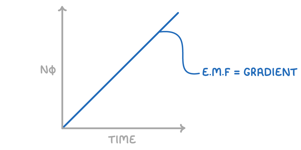
This principle is encapsulated in Faraday's law:
$\epsilon=-\frac{N\Delta\phi}{\Delta t}$
Where:
- ε = induced EMF (V)
- N = number of turns in a coil
- φ = magnetic flux (Wb)
- t = time (s)
This law implies that a greater change in flux over a given time, or more turns in the coil, will result in a higher induced EMF.
Determining magnetic flux
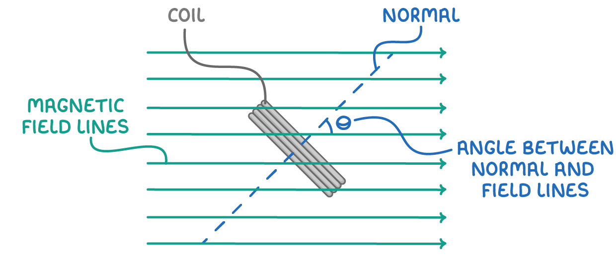
The magnetic flux (φ) through an area (A) perpendicular to the magnetic field (B) is given by:
φ = B A
Where:
- φ = magnetic flux (Wb)
- B = magnetic flux density (T)
- A = area (m2)
When considering multiple turns of a coil, flux linkage becomes relevant:
flux linkage = N φ
For flux at an angle θ to the normal of the area, the equation adjusts to:
flux linkage = B A N cos θ
Calculating induced EMF using Faraday's law
A coil with 100 turns experiences a change in flux from 2 mWb to 0.5 mWb over 0.5 seconds. Calculate the induced EMF.
Step 1: Determine change in flux
Initial flux = 2 mWb
Final flux = 0.5 mWb
Flux change = Initial - Final = 2 - 0.5 = 1.5 mWb
Step 2: Formula
$\epsilon = -\frac{\text{N}\Delta\phi}{\Delta \text{t}}$
Step 3: Substitution and correct evaluation
$\epsilon= - \frac{100\times1.5\times10^{-3}}{0.5}=0.3 \text{ }V$
Worked Example - Calculating induced EMF in a rotating coil
A coil with 200 turns is placed in a magnetic field of 0.5 Tesla. The coil's area is 0.1 m2. Initially, the coil is perpendicular to the magnetic field. It is then rotated to a position where its plane is parallel to the magnetic field in 0.2 seconds. Calculate the average induced EMF during this period.
Step 1: Calculate initial and final flux linkage
Initial position (perpendicular):
φ = B A = 0.5 x 0.1 = 0.05 Wb
Final position (parallel):
φ = 0 Wb
Step 2: Calculate change in flux linkage
$Δ\phi = \phi_\text{final} - \phi_\text{initial} = 0 - 0.05 = -0.05 \text{ Wb}$
Step 3: Formula
$\epsilon\text{ = }\frac{\text{N }\Delta\phi}{\Delta \text{t}}$
Step 4: Substitution and correct evaluation
$\epsilon\text{ = }\frac{200\times0.05}{0.2}\text{ = 50 V}$