17.7 - Investigating Resistance
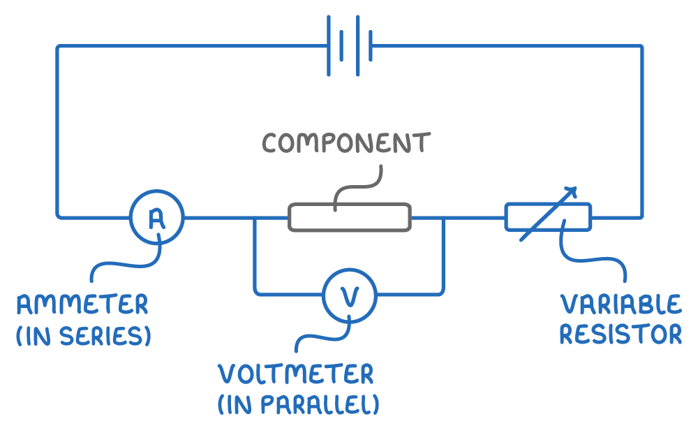
The standard test circuit
-
To find out how a component behaves, its current and potential difference are measured at the same time using a standard test circuit.
-
The same circuit works for a fixed resistor, a filament lamp or a diode.
-
Ammeter - Measures the current through the component, in amps. Placed in series with the component, so the same current passes through both. It can go anywhere along the main circuit, but never in parallel.
-
Voltmeter - Measures the potential difference across the component, in volts. Placed in parallel with the component being tested, not across the battery or any other part.
Taking the readings
- Connect the component and the ammeter in series, with the voltmeter in parallel across the component.
- Vary the current through the component - usually by adjusting a variable resistor in series, as shown below, or by changing the output potential difference of the power supply.
- Record several pairs of current and potential difference readings as the current is changed.
- For each pair, calculate the resistance (). This shows whether the resistance stays constant or changes with current.
Keeping the results reliable
- The component can heat up as current flows, and a change in temperature changes its resistance.
- Keep the current low, and disconnect the circuit to cool between readings if it starts to warm up.
- Repeat each reading and calculate a mean.
Finding the I-V characteristics of components
The standard test circuit is used to find the current-voltage characteristic of three components: a fixed resistor at constant temperature, a filament lamp and a diode.
- Set up the standard test circuit with the chosen component in place.
- Take several pairs of current and potential difference readings as the current through the component is varied.
- Plot current against potential difference for that component.
Adapting the method for each component
- Resistor - Keep the temperature constant by using low currents, so the line isn't bent by heating.
- Filament lamp - Let the temperature rise as normal, since the point is to see how its resistance changes when it heats up.
- Diode - After taking readings one way round, reverse the diode connections. Almost no current flows in reverse, showing the diode only conducts one way.
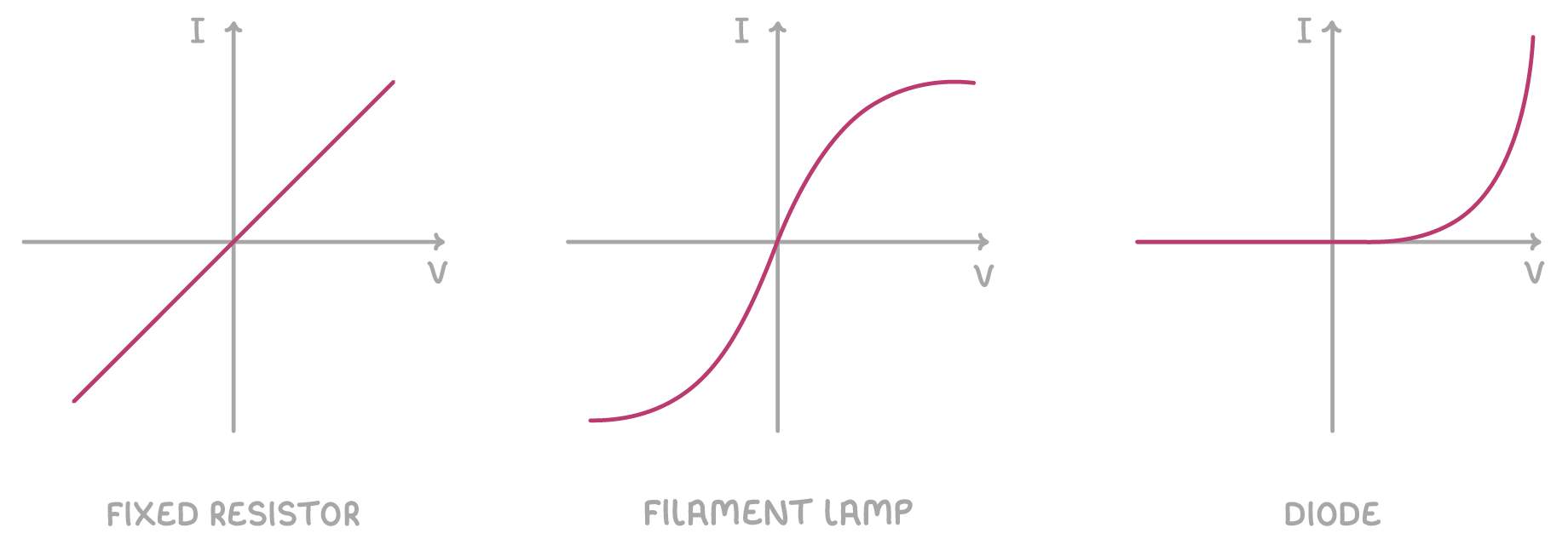
The three characteristics: a straight line, an S-shaped curve, and one-way conduction.
Using voltmeters and ammeters correctly
Voltmeters measure potential difference
- Choose a suitable range on an analogue voltmeter, or the appropriate setting on a digital meter.
- Connect the voltmeter in parallel across the component being tested.
- Connect the red lead to the positive terminal and the black lead to the negative terminal.
- Read the potential difference from the scale or digital screen.
Ammeters measure current
- Choose a suitable range on an analogue ammeter, or the appropriate setting on a digital meter.
- Connect the ammeter in series with the component on the same branch of the circuit.
- Connect the red lead to the positive terminal and the black lead to the negative terminal.
- Read the current from the scale or digital screen.