7.5 - Series & Parallel Circuits
The experiment
Aim
To find out what happens to the current, the potential difference, and the brightness of the components as they are connected first in series and then in parallel.
Background
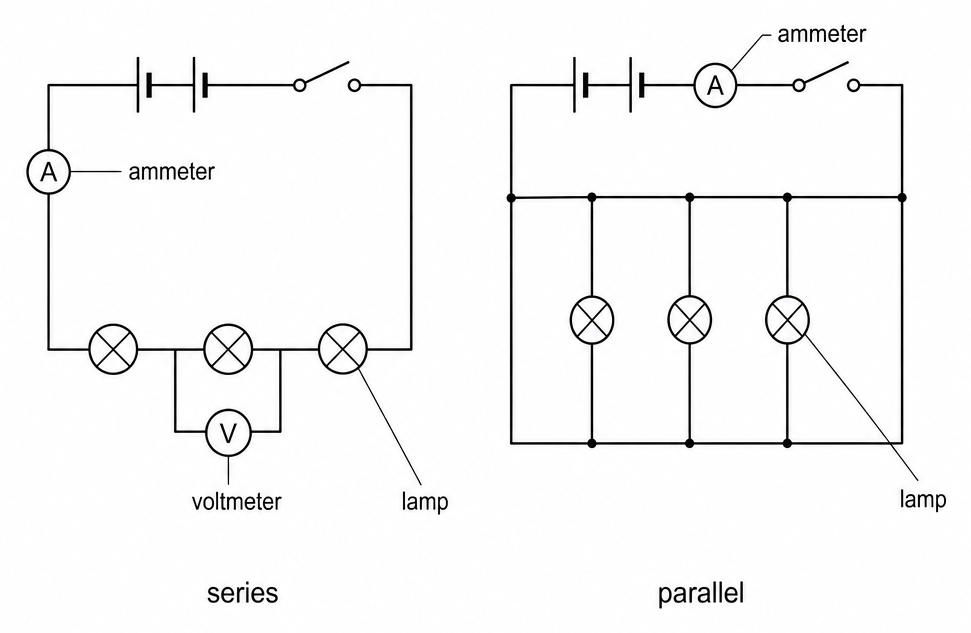
- In a series circuit there's one loop, so the same current flows through every component and the supply potential difference is shared between them. Each component added increases the total resistance.
- In a parallel circuit each component is on its own branch, so each gets the full supply potential difference and the current splits between the branches. Each branch added lowers the total resistance.
- You can't see how the current and potential difference are shared out, but you can measure them with an ammeter and a voltmeter.
- So in this practical you add identical components in series and then in parallel, measure the current and potential differences, and work out the total resistance.
Variables
- Independent variable - Whether the components are in series or in parallel, and how many there are.
- Dependent variables - The current, and the potential difference across each component.
- Control variables - The power supply setting, and identical components.
Method
- Build a series circuit - Connect the power supply, a switch, an ammeter, and one lamp in one loop, with a voltmeter across the lamp. Record the current, the potential difference, and how bright the lamp is.
- Add lamps in series - Add a second and then a third identical lamp. Each time, record the current and the potential difference across each lamp, and note the brightness.
- Test the series circuit - Move the ammeter to a different place in the loop and check the reading. Then unscrew one lamp and see what happens.
- Build a parallel circuit - Start again with one lamp, then add a second and a third, each on its own branch.
- Take parallel readings - Each time, record the potential difference across each lamp, the current in each branch, the total current, and the brightness. Then unscrew one lamp and see what happens.
- Repeat with resistors - Connect one 10 Ω resistor across the supply, then two in series, then two in parallel, recording the potential difference and the current each time.
Safety
- Ammeters in series only - An ammeter has almost no resistance, so connecting one across a component or the supply short-circuits it and can damage the meter and the power supply.
- Hot lamps - Let lamps cool before you unscrew them.
Worked example - Series and parallel readings
A student used a 6.0 V supply and identical lamps, first in series and then in parallel.
In series
| Number of lamps | 1 | 2 | 3 |
|---|---|---|---|
| Potential difference across each lamp (V) | 6.0 | 3.0 | 2.0 |
| Current in the circuit (A) | 0.30 | 0.15 | 0.10 |
In parallel
| Number of lamps | 1 | 2 | 3 |
|---|---|---|---|
| Potential difference across each lamp (V) | 6.0 | 6.0 | 6.0 |
| Current in each branch (A) | 0.30 | 0.30 | 0.30 |
| Total current from the supply (A) | 0.30 | 0.60 | 0.90 |
They then connected 10 Ω resistors across the same supply.
| Arrangement | One resistor | Two in series | Two in parallel |
|---|---|---|---|
| Current (A) | 0.60 | 0.30 | 1.20 |
Check the readings against the rules for each type of circuit, and work out the total resistance in each case.
Step 1 - Check the series potential differences
With three lamps, 3 × 2.0 = 6.0 V, the supply potential difference. Potential differences across components in series add up to the supply potential difference.
Step 2 - Work out the total resistance in series
Divide the supply potential difference by the current.
Each extra lamp adds another 20 Ω, so resistances in series add together.
Step 3 - Check the parallel currents
With three lamps, 3 × 0.30 = 0.90 A, the total current from the supply. The branch currents add up to the total current.
Step 4 - Work out the total resistance in parallel
That's less than one lamp's 20 Ω. Each extra branch gives the charge another route, so more current flows for the same potential difference, which means a smaller total resistance.
Step 5 - Compare two resistors in series and in parallel
- One resistor on its own gives 6.0 ÷ 0.60 = 10 Ω.
- Two in series give 6.0 ÷ 0.30 = 20 Ω, which is 10 + 10.
- Two in parallel give 6.0 ÷ 1.20 = 5.0 Ω, half the resistance of one.
The total resistance of resistors in parallel is always less than the smallest resistance on its own.
Resistors give a cleaner check than lamps. A real filament lamp wouldn't give the same 20 Ω at every current, as the lamps above do, because its resistance climbs as it heats up.
Common exam questions
Question 1
Why do lamps get dimmer as more are added in series, but not in parallel?
In series, the potential difference is shared between more lamps and the current falls. In parallel, every lamp still gets the full supply potential difference and the same current.
Question 2
When one lamp is unscrewed, the others go out in a series circuit but stay lit in a parallel circuit. Why?
A series circuit is a single loop, so removing a lamp breaks the only path. In a parallel circuit, the other branches are still complete circuits.
Question 3
Where would you put an ammeter to measure the current through one lamp in a parallel circuit?
In series with that lamp, on its branch. In the main part of the circuit, it reads the total current.
Question 4
Why must the components be identical?
So any change in the readings is caused only by how many there are and how they're connected. Components with different resistances would take different shares of the potential difference.
Question 5
Why do fixed resistors give clearer results than filament lamps?
A resistor keeps the same resistance whatever the current. A filament lamp's resistance rises as it heats up, so the totals worked out with R = V ÷ I change as the circuit changes.