7.4 - Resistance of a Wire
The experiment
Aim
To find out how the length of a wire affects its resistance.
Background
- Resistance is how strongly something opposes the current flowing through it.
- A current is electrons moving through the wire, and as they go they collide with the metal ions.
- A longer wire means more collisions before the electrons reach the far end, so its resistance is higher.
- You can't measure resistance directly, but you can measure the potential difference across the wire and the current through it, and work the resistance out with .
- So in this practical you find the resistance of different lengths of the same wire, and plot resistance against length to see how they're related.
Variables
- Independent variable - The length of wire between the crocodile clips.
- Dependent variable - The resistance of that length, worked out from the current and the potential difference.
- Control variables - The thickness and material of the wire, and its temperature.
Method
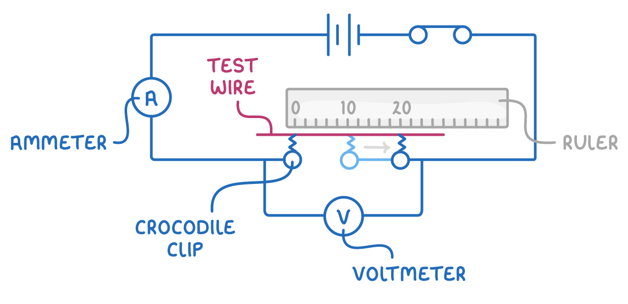
- Set up the wire - Tape a length of thin resistance wire straight along a metre ruler.
- Build the circuit - Connect the power supply, a switch, and an ammeter in series, with two crocodile clips leading to the wire. Connect the voltmeter in parallel across the wire between the clips, and nothing else.
- Set a low voltage - Set the power supply to about 1 V.
- Clip on the first length - Attach one crocodile clip level with the 0 cm mark, and the other at 20 cm.
- Take readings - Close the switch, record the current and the potential difference, then open the switch straight away.
- Change the length - Move the second clip along 20 cm at a time, taking readings at each length up to 100 cm.
- Plot the graph - Work out the resistance at each length, and plot resistance against length with a line of best fit.
Worked example - Resistance and length of a wire
A student measured the current and the potential difference for five different lengths of the same wire.
| Length (cm) | 20 | 40 | 60 | 80 | 100 |
|---|---|---|---|---|---|
| Potential difference (V) | 0.50 | 0.80 | 1.05 | 1.20 | 1.30 |
| Current (A) | 0.50 | 0.40 | 0.35 | 0.30 | 0.26 |
Find the resistance at each length, describe what the graph shows, and use it to predict the resistance of a 150 cm length of the same wire. Then explain what would happen to the graph if the first crocodile clip had been attached at the 2 cm mark instead of 0 cm.
Step 1 - Work out the resistance at each length
Use for each length.
- At 20 cm, 0.50 ÷ 0.50 = 1.0 Ω.
- At 40 cm, 0.80 ÷ 0.40 = 2.0 Ω.
- At 60 cm, 1.05 ÷ 0.35 = 3.0 Ω.
- At 80 cm, 1.20 ÷ 0.30 = 4.0 Ω.
- At 100 cm, 1.30 ÷ 0.26 = 5.0 Ω.
Step 2 - Plot the graph and describe it
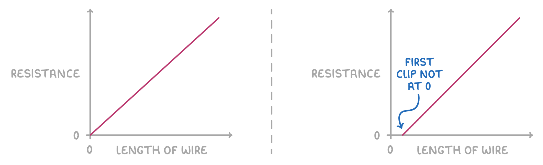
Plot resistance on the y-axis against length on the x-axis. The points lie on a straight line through the origin, so resistance is directly proportional to length. Doubling the length doubles the resistance.
Step 3 - Use the gradient to predict a resistance
The gradient is the resistance for each centimetre of wire.
A 150 cm length of the same wire has a resistance of 0.050 × 150 = 7.5 Ω. The prediction works because the line is straight and passes through the origin.
Step 4 - Explain a line that misses the origin
With the first clip at the 2 cm mark, the wire between the clips is 2 cm shorter than each recorded length. Every point moves 2 cm to the right, so the line crosses the length axis at 2 cm instead of passing through the origin.
This is a systematic error. It affects every reading by the same amount, so repeating the experiment won't remove it. The gradient is still correct, because moving every point by the same amount doesn't change the slope.
Common exam questions
Question 1
Why is the power supply set to a low voltage, and the switch opened between readings?
A current warms the wire, and a hotter wire has a higher resistance. A low voltage gives a small current that heats the wire less, and opening the switch lets it cool, so its temperature stays the same.
Question 2
Why must the voltmeter be connected across the test wire only, and not across the whole circuit?
The resistance being measured is the wire's. Across the whole circuit, the voltmeter would include the potential difference across the other components, so the calculated resistance would be too high.
Question 3
Why is the same wire used for every length?
A thicker wire has a lower resistance, and different metals resist the current by different amounts. Changing the thickness or the material would change the resistance for a reason other than the length.
Question 4
Why is the wire taped straight along the ruler?
So the length read off the ruler is the true length of wire between the clips. A kinked wire is longer than the reading, so every resistance would look too high for its length.
Question 5
How would you change this experiment to investigate how the thickness of a wire affects its resistance?
Use wires of the same material and length but different cross-sectional areas. The cross-sectional area becomes the independent variable.