7.3 - I-V Characteristics of Components
The experiment
Aim
To find out how the current through a component changes as the potential difference across it is changed, and to use the graph of the results to work out how the component's resistance behaves.
Background
- Resistance is how strongly a component opposes the current through it. It's linked to the potential difference and the current by .
- A fixed resistor, or a wire at a steady temperature, keeps the same resistance, so the current is directly proportional to the potential difference.
- A filament lamp heats up as the current rises, and its resistance goes up with it.
- A diode only lets current through in one direction.
- You can't measure resistance directly, but you can measure the potential difference and the current, and work it out from them.
- So in this practical you measure the current at a range of potential differences, in both directions, and plot the component's I-V characteristic. Its shape shows how the resistance behaves.
Variables
- Independent variable - The potential difference across the component.
- Dependent variable - The current through the component.
- Control variables - The component, the meters, and, for a resistor or a wire, its temperature.
Method
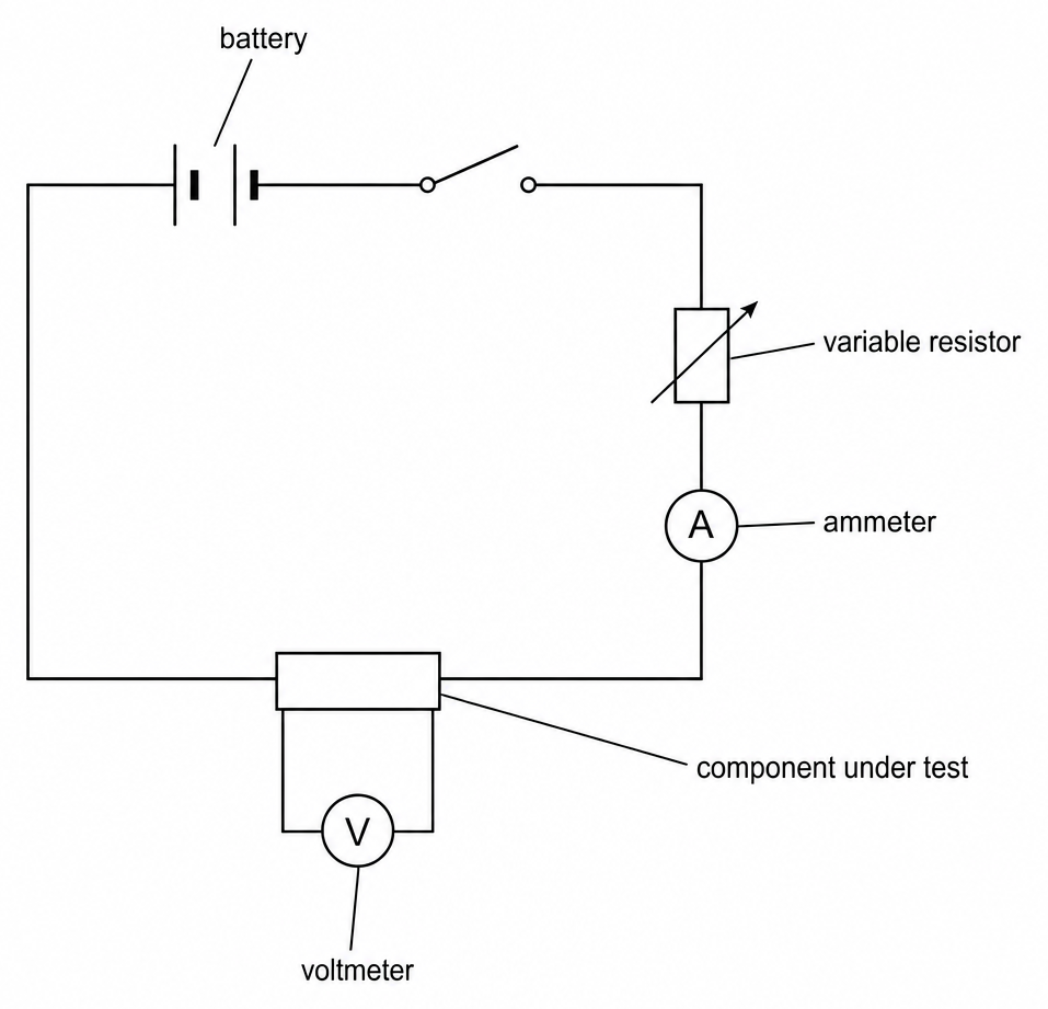
- Build the circuit - Connect the component in series with an ammeter, a variable resistor, a switch, and the power supply, and connect a voltmeter in parallel across the component.
- Take the first reading - Set the variable resistor to its highest resistance, close the switch, and record the current and the potential difference. Then open the switch.
- Take more readings - Lower the resistance a step at a time, opening the switch after each pair of readings, until you have at least six pairs.
- Reverse the current - Swap the leads at the power supply and repeat steps 2 and 3. Both meters now read negative.
- Plot the graph - Current on the y-axis against potential difference on the x-axis, including the negative readings, with a line of best fit.
- Test each component - A fixed resistor, a length of wire, a filament lamp, and a diode. For the diode, add a fixed resistor in series and use a milliammeter.
Safety
- Hot components - A filament lamp, or a resistor carrying too much current, can get hot enough to burn. Use a low-voltage d.c. supply, keep the settings low, and let everything cool before you change the circuit.
Worked example - Resistance of a resistor and a lamp
A student tested a fixed resistor and recorded these readings.
| Potential difference (V) | 1.0 | 2.0 | 3.0 | 4.0 | 5.0 | 6.0 |
|---|---|---|---|---|---|---|
| Current (A) | 0.25 | 0.50 | 0.75 | 1.00 | 1.25 | 1.50 |
They then tested a filament lamp, which gave 0.20 A at 1.0 V and 0.60 A at 6.0 V.
Find the resistor's resistance from one pair of readings and then from the graph, and say why the graph is better. Then find how the lamp's resistance changes, and how to find the resistance at a point on a curve.
Step 1 - Find the resistance from one pair of readings
Take the pair at 4.0 V and 1.00 A.
Step 2 - Find the resistance from the gradient
Plot current on the y-axis against potential difference on the x-axis. The points lie on a straight line through the origin.
With current on the y-axis, the gradient is , which is .
The gradient uses all the points, so it reduces the effect of random errors and gives a better value than one pair.
Step 3 - Find the lamp's resistance as the current rises
The resistance doubles. As the current increases, the filament heats up and its ions vibrate more, so the electrons collide with them more often.
Step 4 - Find the resistance at a point on a curve
The gradient of a curve changes along it, so don't use it. Read V and I off the graph at that point, and work out .
Common exam questions
Question 1
Why is the ammeter connected in series with the component, but the voltmeter in parallel with it?
The ammeter needs the same current through it as the component, which only happens in series. The voltmeter measures the potential difference between the component's two ends, so it goes across it.
Question 2
Why is the switch opened between readings?
A current warms the component, and a warmer wire or resistor has a higher resistance. Opening the switch lets it cool, so its temperature doesn't change the results.
Question 3
Explain the shape of the I-V graph for a filament lamp.
As the current increases, the filament gets hotter and its resistance increases. Each extra volt gives a smaller increase in current, so the line bends over.
Question 4
Why is a fixed resistor put in series with a diode when it's tested?
Once a diode conducts, its resistance is very low, so the current could rise high enough to damage it. The fixed resistor keeps the current down.
Question 5
Why are the leads at the power supply swapped over partway through?
To reverse the current and get readings for negative potential differences. Without them, you couldn't show that a diode conducts in one direction only.