2.5 - Series Circuits
What a series circuit is
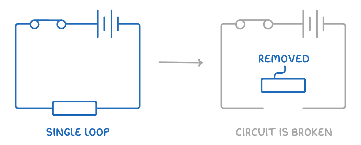
- In a series circuit, the components are connected end to end in a single loop between the positive and negative ends of the power supply.
- If one component is removed or breaks, the circuit is broken and all the components stop working.
Connecting meters
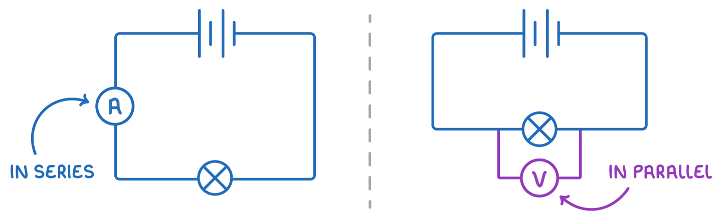
- An ammeter is connected in series, so the current it measures flows through it.
- A voltmeter is connected in parallel across a component.
Series rules - Potential difference, current and resistance
Potential difference is shared
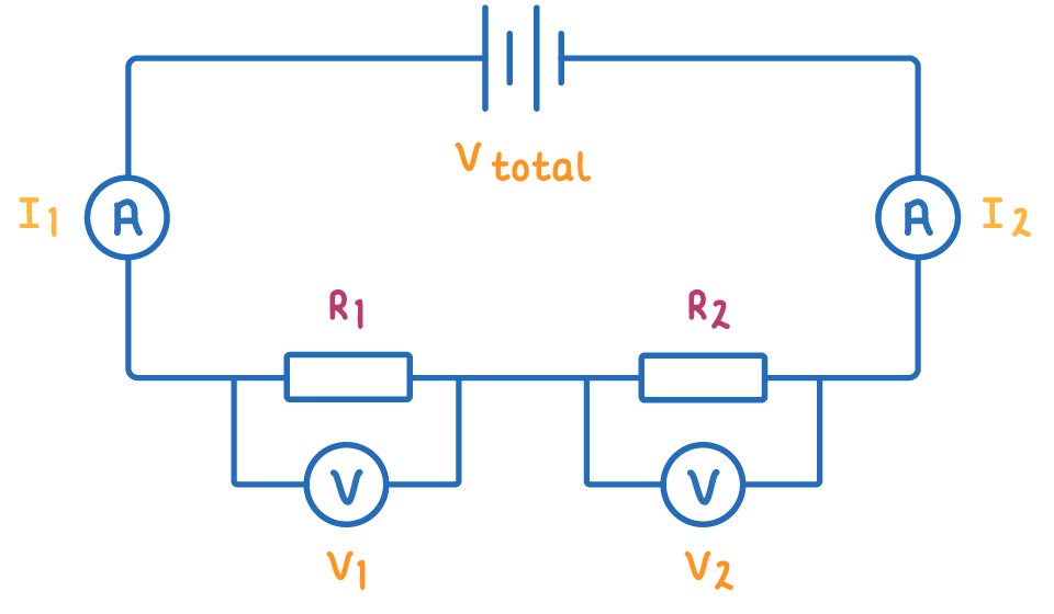
The total potential difference of the supply is shared between the components:
The bigger a component's resistance, the bigger its share of the total potential difference.
Current is the same everywhere
The same current flows through every part of a series circuit:
The size of the current depends on the total potential difference and total resistance ().
Resistance adds up
The total resistance is the sum of the individual resistances:
Adding another resistor in series increases the total resistance, reducing the total current.
Worked example - Current in a series circuit
A 24 V supply is connected in series with two resistors of 3 Ω and 5 Ω. Calculate the current in the circuit.
Step 1 - Find the total resistance
The resistors are in series, so add them:
Step 2 - Rearrange to make the subject
Step 3 - Substitute the values
Use the supply voltage and the total resistance:
The current is 3 A, and because this is a series circuit, the same 3 A flows through both resistors.
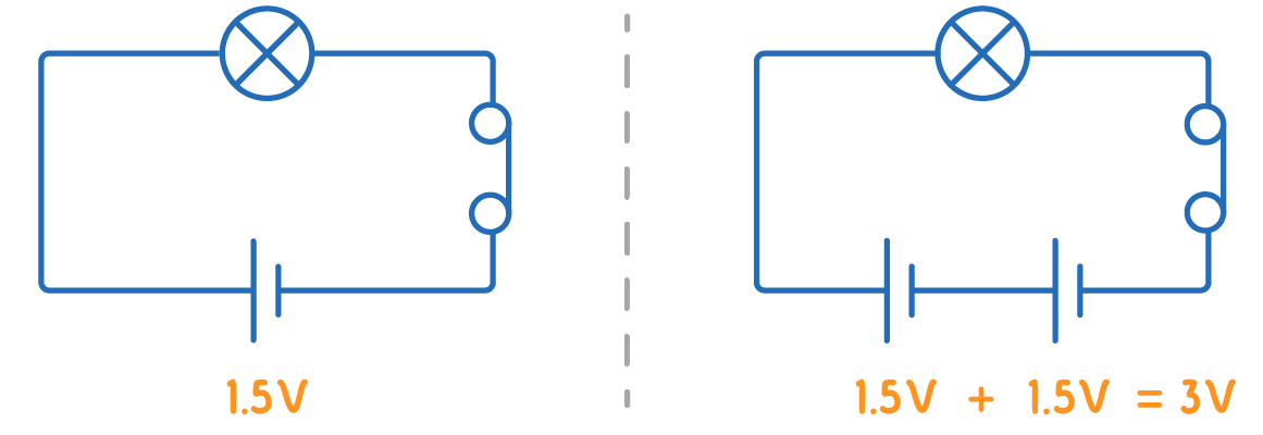
Cell potential differences add up in series
- When cells are connected in series the same way round (the positive terminal of one to the negative terminal of the next), their potential differences add together.
- For example, two 1.5 V cells connected in series supply a total of 3 V.