2.1 - Circuits Introduction
Current, potential difference and resistance
Three quantities describe what's happening in an electric circuit:
- Current - The rate of flow of electric charge. In a metal, the charge is carried by electrons. Symbol .
- Potential difference (voltage) - The energy transferred per unit of charge, which pushes charge around the circuit. Symbol .
- Resistance - How much a component opposes the flow of charge. Symbol .
Conditions for current to flow
Charge only flows as a current when both conditions are met:
- The circuit is complete (closed) with no gaps.
- There is a source of potential difference, such as a cell or battery.
In a single closed loop, current has the same value everywhere.
How the three are linked
Current through a component depends on both the potential difference across it and its resistance:
- Increasing the potential difference increases the current (if resistance is fixed).
- Increasing the resistance decreases the current (if potential difference is fixed).
Circuit diagrams and standard symbols
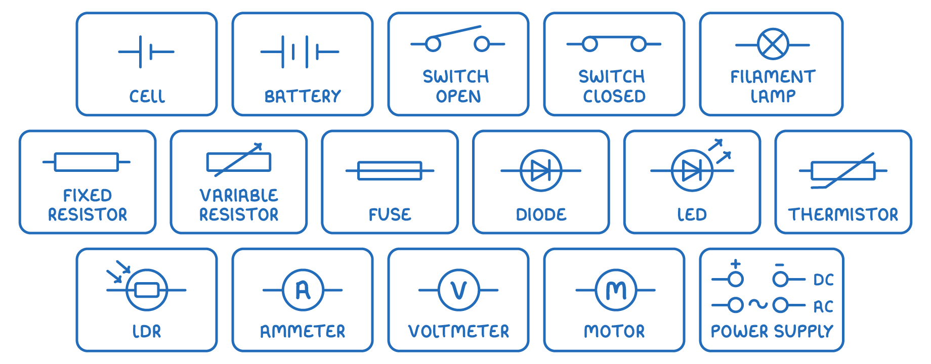
Circuits are drawn using standard symbols connected by straight lines:
- Cell and battery (two or more cells joined together)
- Switch (open and closed)
- Filament lamp
- Fixed resistor and variable resistor
- Fuse
- Diode and LED (light-emitting diode)
- Thermistor and LDR (light-dependent resistor)
- Ammeter and voltmeter
- Power supply
- Motor
In a cell symbol, the long line is the positive terminal and the short line is the negative terminal.
TermDefinition
CurrentThe rate of flow of electric charge.
ResistanceHow much a component opposes the flow of charge through it, equal to the potential difference across it divided by the current through it.
Key points to remember
How were these notes?