5.6 - Lenses
- 1
The principles of converging lenses
- 2
How to construct and interpret ray diagrams
- 3
The distinction between real and virtual images
- 4
The lens equation and its application
- 5
How to calculate power
- 6
How to calculate magnification
Converging and diverging lenses
Lenses refract light, which means they change the direction light rays are travelling in.
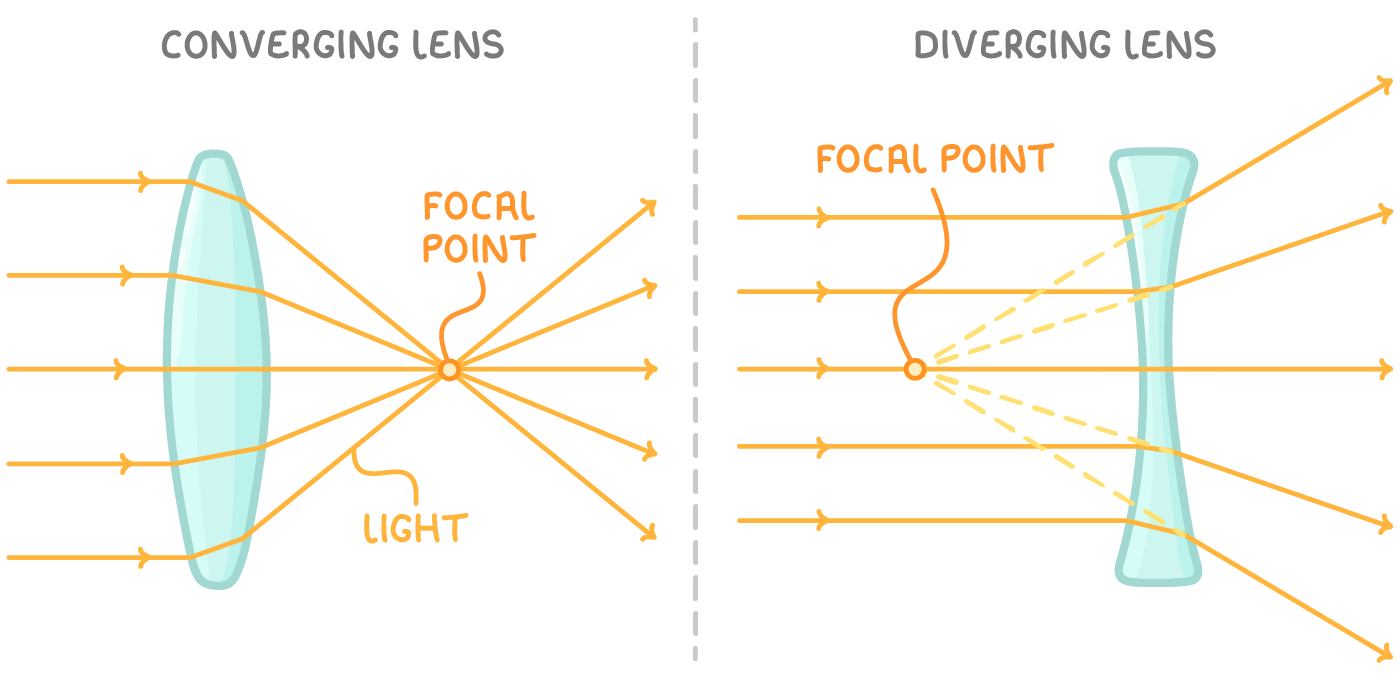
There are two main types of lenses:
- Converging lenses
- These are convex in shape (thicker in the middle than at the edges).
- They alter the path of light rays through refraction, causing them to bend towards each other.
- Diverging lenses
- These have a concave shape (thicker at the edges than in the middle).
- They cause light rays to disperse or ‘diverge’, making them appear as if they originated from a focal point in front of the lens.
How to represent converging and diverging lenses in ray diagrams
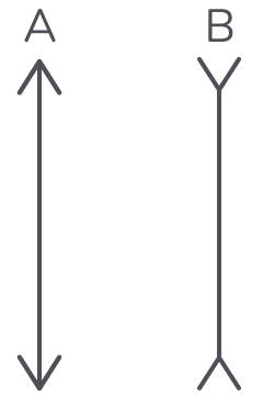
Converging and diverging lenses are displayed differently in ray diagrams:
- Converging (convex) lens - This is represented with arrow heads pointing outwards, like 'A' in the image above.
- Diverging (concave) lens - This is represented with arrow heads pointing inwards, like 'B' in the image above.
Ray diagrams
Ray diagrams are useful to visualise the behaviour of light as it passes through lenses. They allow us to determine the location, size, and type of image produced by a lens.
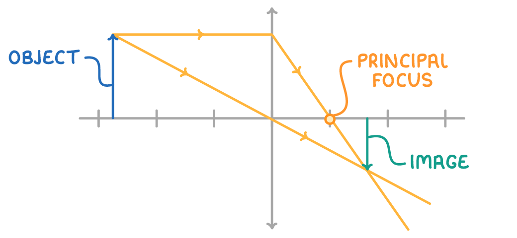
Key terms in lens geometry:
- Principal axis - The horizontal line passing through the centre of the lens.
- Lens axis - The vertical line passing through the centre of the lens (this one's showing a convex lens).
- Principal focus (focal point) - The point on the principal axis where axial rays that are parallel to the principal axis converge.
- Focal plane - The plane perpendicular to the principal axis that contains the principal focus.
- Focal length (f) - The distance between the lens axis and the focal plane.
Note: Sometimes ray diagrams show two focal points along the principal axis. One is after the lens (as in the ray diagram above), and the other one is the same distance from the lens axis, but before the lens instead of after it. You can use the focal point before the lens to work out where diverging lenses will refract light rays that are parallel to the principal axis to.
Constructing converging lens ray diagrams
Ray diagrams are vital tools for understanding image formation through lenses.
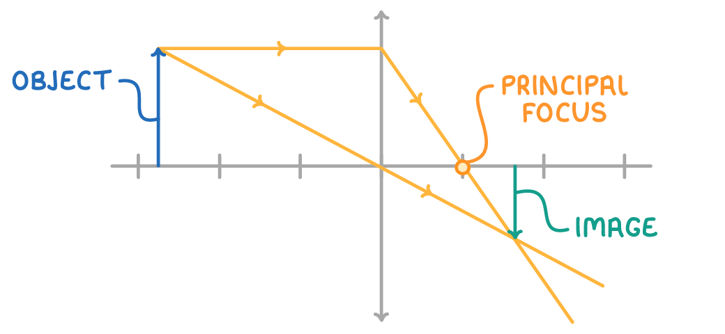
To construct a ray diagram:
- Draw the lens and its principal axis
- Place the object on or above the principal axis
- Draw two rays from the top of the object:
- One parallel to the principal axis, then bending through the principal focus
- One passing straight through the centre of the lens (the origin) without bending
- The intersection of these rays indicates the top of the image
Real images
Real images are formed when light rays from a point on an object pass through another point in space.
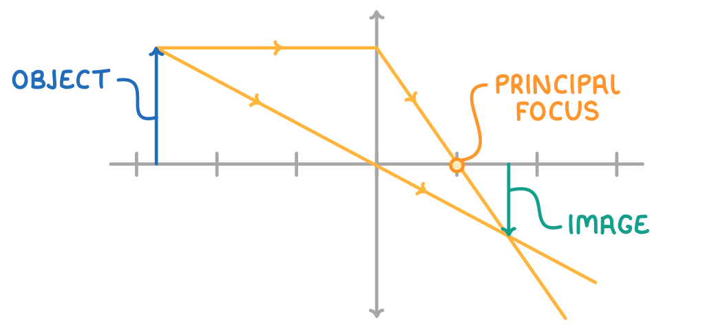
Key points:
- The rays converge at the image location.
- Real images can be captured on a screen.
- The images formed are inverted (upside down) compared to the object.
- Real images are formed when the object is placed further than the focal length of a converging lens.
- Real images cannot be formed by a diverging lens.
Virtual images
Virtual images are formed when light rays from a point on an object appear to come from another point in space.
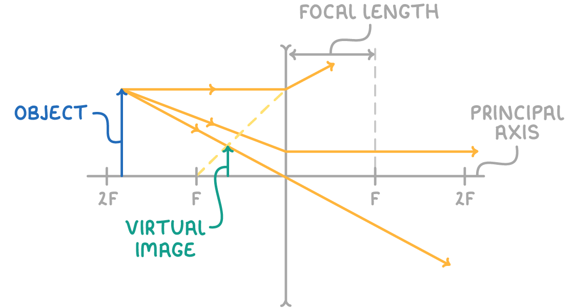
Key points:
- The light rays do not converge at the image location; they only appear to diverge from it.
- Virtual images cannot be captured on a screen.
- Virtual images are upright (the same way up) compared to the object.
- Diverging lenses always from virtual images at their focal point before the lens.
- Converging lenses form virtual images when the object is placed closer to the lens than the focal length.
The lens equation
The lens equation relates the object distance (u), image distance (v), and focal length (f):
Where:
- f = focal length of the lens (m)
- u = object distance from the lens (m)
- v = image distance from the lens (m)
Note: v is positive for real images and negative for virtual images.
Worked example - Applying the lens equation
A converging lens with a focal length of 15 cm forms an image of an object placed 20 cm from the lens. Calculate the position of the image.
Step 1: Identify known values
- f = 15 cm = 0.15 m
- u = 20 cm = 0.20 m
- v = unknown (to be calculated)
Step 2: Formula
Step 3: Substitute known values
Step 4: Solve for v
v = = 0.6 m = 60 cm
A real image is formed 60 cm from the lens.
How to calculate power
The power of a lens (P) is a measure of its ability to converge or diverge light and is given by the formula:
Where:
P = power of the lens in diopters (D)
f = focal length of the lens (m)
Thicker lenses have a smaller focal length, so they have a larger power.
Combining lenses
When multiple lenses are placed in close proximity, their combined power is the sum of their individual powers.
Magnification
Lenses can produce:
- A magnified image - This image will appear larger than the object itself.
- A diminished image - This image will appear smaller than the object itself.
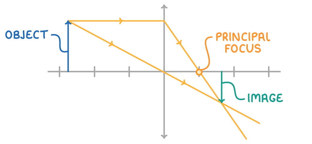
For example, in the diagram above, the size of the image is diminished relative to the size of the object (the cyan arrow is shorter than the blue arrow).
Calculating magnification
We can calculate the magnification of an image produced by a lens using the following formula:
Where:
m = magnification
v = image height
u = object height
Note: As magnification is a ratio, it doesn't have any units. However, it's important to make sure the units for image and object height are the same when calculating magnification.