6.6 - Potential divider
- 1What a potential divider circuit is and its purpose
- 2Calculating the output voltage of a potential divider
- 3Choosing resistance values to obtain a desired output voltage
- 4Using a potential divider for voltage calibration
- 5Issues with connecting a low resistance load
Introduction to the potential divider
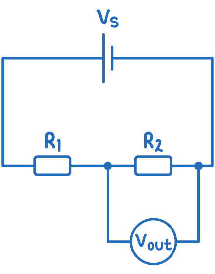
A potential divider is a simple circuit containing resistors in series, across which the source voltage is divided. It allows only a fraction of the total voltage to be used a the output voltage.
Calculating the output voltage
The output voltage (Vout) depends on the resistor values and input voltage (Vs) according to this equation:
Where:
- Vout = output voltage (V)
- R = resistance of resistor 1 ()
- R2 = resistance of resistor 2 ()
- Vs = source voltage (V)
So the output voltage is always a fraction of the input voltage, determined by the resistor ratio.
Worked example - Calculating output potential
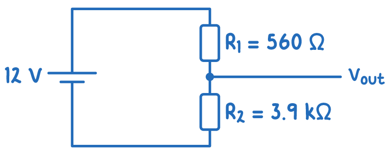
Calculate Vout for a potential divider with R1 = 560 Ω, R2 = 3.9 kΩ, and Vs = 12 V.
Step 1: Formula
Step 2: convert k to
to convert from k to Ω, multiply by 1,000
3.9 k = 3,900
Step 3: Substitution and correct evaluation
How were these notes?